
In this section we will take a look at some of the hardware used in a node site.
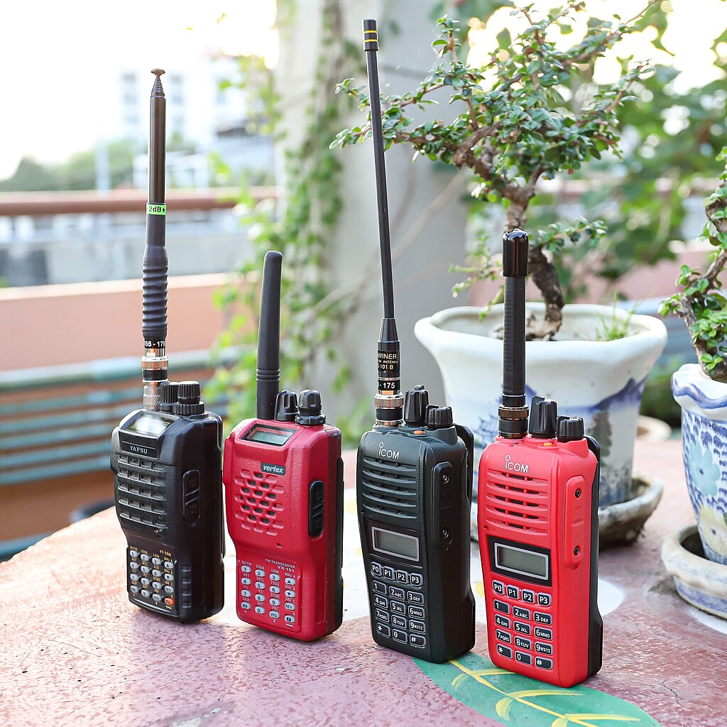
AREDN® is one of the lowest cost parts of the service. The radios are not expensive, with the most costly being the sector antennas (the long vertical boxes you see on cell site towers) and some of the very high gain directional antennas. As we obtain high locations for node stacks (sites with multiple nodes like a tower, water tower or tall building) the average user will be able to use a Mikrotik hAP ac lite which will cost around $50 on average but can be found as low as $41 but you may at times find them no lower than about $57, a very volatile market. The hAP will function as a router and 5 port switch. The radios on your tower, pole or whatever structure you use to reach the node stacks will usually have 1 or 2 Ethernet ports on them. They are powered using PoE but it is of the older nonmanaged PoE, which runs no more than about 30vdc. The radios you will need for your RF link may range from a radio that Mikrotik sells which will allow you to re-purpose a satellite dish for a high gain RF path. NOTE, there are several publications that when this configuration is used one should not get into the beam path. Also high gain (30db) dishes which cost about $120 for the dish and about the same for the radio used with the dish. Most of these devices have several radio options, so the dish and radio are sold separately. You may also have a good site with tower and want to offer access to your neighbours and others more distant but who have a good path to your tower so you may install sector antennas. The sector antennas rather than concentrating all of the RF into a narrow beam for Point to Point links have a wider beam coverage, usually in 60, 90 or 120 degree beam widths. Of course the wider then beam path the lower the gain. Let us look at some configurations. First some of the parts:

You may plug your home lan into this port. It is used to provide for a tunnel or access to the device from your local public network.
The 3 middle ports framed in black are the AREDN® LAN ports for your devices you want on the AREDN® LAN. The right most port framed in yellow is the DtD or Device to Device port, this is where your outside antenna will be connected. If there are more than one, a dumb switch will allow for multiple radio connections. The cable used in all of this is standard cat5/6 cable using the standard connector format with RJ-45 connectors. No coax!!!

This is the LHG series radios, the 5 series have in most cases a 24 db gain antenna on them RF power is about .5Watts, the EIRP is right at 100W. Do not put it in front of your face when powered up either. There is a higher cost version of this antenna which has 27 db of gain which gives EIRP 250W.
These antennas range from about $67 for the 24 dB gain version to $100 +/- $10 for the larger version.
These are easy antennas to install and provide good gain for a good price. They are also very easy to use mobile. The screen allows the wind to go through them but sends the 5Ghz RF the right direction. There is also a 2.4Ghz unit, the gain is somewhat lower but 2.4Ghz penetrates trees better, the only drawback is there are only two non-part 15 channels the rest of the part 97 band is shared with part 15, and it is very noisy.

There are other antennas such as the SXT series seen below, this antenna is available for $39 right now, that price will probably change, as they do fluctuate. This antenna has about 16 db of gain so it will give good performance linking to a sector antenna up to about 5 miles distance.
Looking at some other products, one which comes up quite a bit is Ubiquiti. We have several of those in service, here are some examples:

Litebeam ac5, you want the AC model of these though the older ones are all over the place and well Supported by AREDN® We have several of these in service around the network. The dish gain is 23 dB. These radios actually have two radios in them, the 5Ghz radio which is the point to point (PtP) radio and a 2.4Ghz radio which is sort of and administrative WiFi radio. You can use the Chart function built into the node to align these antennas. You connect a cell phone to the 2.4Ghz WiFi radio, you then open the browser to localnode.local.mesh and go to the chart function on the node status screen, you then turn audio on, now you will hear a tone that follows the signal level, you adjust the antenna for the highest tone pitch. A very handy tool already built into the node. NOTE: if there are two or more links terminating at this antenna you can use the Select Device to select the link you want to measure or align.

Below is the Rocket Dish, it is the antenna only, the radio maybe selected. The original radio was the Ubiquiti Rocket M5. Until recently we had one in a link to the node stack in downtown OKC. It has been replaced with a Rocket R5AC

This is the Rocket R5AC-lite. The two black connection points are where the antenna goes connected via two short coax jumpers. The R5AC-lite is mounted on the rear of the dish, there are special support rails and a hood that form part of the antenna along with the mounting hardware.
One last antenna that is used for multiple access is the sector antenna, it functions as a point to multipoint antenna, mounted on a tower, water tower, rooftop, or other structure. It gives access to multiple users within the coverage of the antenna.

This is a Mikrotik Sector antenna, it may have a 60 degree beam width, a 90 degree beam width, or 120 degree beam width. As the beam width increases the gain drops. You choose the antenna to fit the coverage.
We generally do not use omnidirectional antennas, the gain just is not that good and you get into hidden terminal problems with them.
Now let us put the parts together for a simple node stack

Here we have a directional antenna, an LHG5 which will be aimed at another antenna either another node site also being a part of the mesh, or an access point for multiple users. The red line is cat5/6 connecting the radio on the tower to the hAP ac lite. This is the DtD or Device to Device circuit, if there are more radios a simple switch in line will allow them all to communicate. More on this later
The green arrows are the LAN ports for connecting devices such as a computer, a camera, VoIP phone, weather station, whatever you want as long as it meets Part 97 rules.
This is a node stack with multiple antennas on the tower/structure, there are two point to point antennas and a sector antenna. This might be an EOC or hospital site.

We can use dumb switches to extend both the LAN port number and the additional antennas. The PoE or Power over Ethernet injector allows 12-30vdc to use the same cable as the data. Most systems run up near 30vdc due to the long run of cable. Again the applications are generally what you will find on the public network.
Here is a picture of the Edmond South node stack antennas on top of the tower:

At present time there are only point to point antennas, notice that all of the antennas on this tower were previously described. The switch rather than being down below is a small box directly behind the large antenna. Below the same antenna you can just make out a small device, it is a Pan Tilt Zoom camera.
Down in the equipment box below is the hAP ac lite, a solar charge controller (this site is solar powered) a Raspberry Pi for gathering data from the charge controller and also functioning as a remote control. The battery resides at the base of the tower.
This is the lower section of the tower, note the solar panel and below that is the control box, the battery box is on the left side on the ground.

This is the control box. The only difference between this setup and a home station is perhaps the power. A home setup would probably use a 24vdc power supply, you might use solar, but most likely you would have it on a separate panel from your ARDEN gear. Your power source would probably be mains power backed up with a battery, ups or solar. It is for emergency communications.

Going from left to right, the fan is seen on the far left, then mounted on a DIN rail is a Raspberry Pi next to it is the hAP ac lite
Lower half going from left to right is a punch down block, 3 breakers for Load (blue breaker on left) Solar panel, middle breaker, and battery, right breaker. Then there is a small device next to the right most breaker, that is an interface between the Raspberry Pi and the charge controller, the blue box on the right.
I used this node stack because all of the equipment is quite easy to view, and associate. A shack system would be the hAP in the shack and the antennas up on the tower.
The added complexity here is the solar power system. But we want the network to operate regardless of the state of the mains power.
Below is a list of common devices and materials used in a node stack. Your future node stack will probably consist of a mix of some of these devices.

In the next part we will look at Services and applications, all of this is just so much hardware without a job to do. Services and applications provide those jobs.
Chuck, KP4DJT


